Arizona 660 XT
- Overview Arizona 660XT
- Health & Safety
- Roll to Roll Operation
- Cleaning & Maintenance
- Flatbed Operation
- Loading Material
- Vacuum Areas
- Measuring the Head Height
- Printing a Nozzle Check
- Printing Rulers
- Operating Panel - General Usage
- Operating Panel - Administrative Usage
- Double Sided Printing
- Maintenance
- Troubleshooting
- Troubleshooting
- Oce User Manual
- Turning the Arizona On, Off & Idle
Overview Arizona 660XT
Arizona 660XT
The Arizona is a dual use machine. Meaning it can print in either Flatbed mode (printing directly to a sheet or flat media) or Roll-to-Roll mode (printing on roll media).
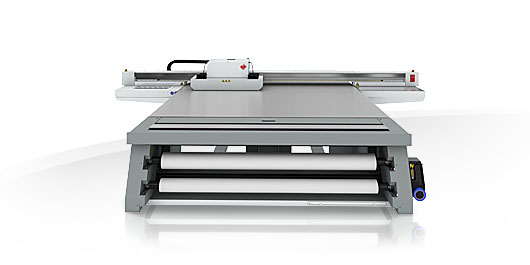
Printer Specifications
| Printing Method | Piezoelectric inkjet |
| Number of nozzles |
1,272 nozzles/channel; 7,632 nozzles total |
| Image technology |
VariaDot® imaging technology |
| Print resolution |
Variable droplet sizes from 6 to 42 picoliters. The result is near-photographic image quality with sharpness only before seen at resolutions of 1,440 dpi or higher. Print perfect text as small as 6 pt. |
Print Speeds (Flatbed Operation)
| Express mode |
64.7 M²/HR |
| Production mode |
49.7 M²/HR |
| Quality mode |
40.0 M²/HR |
| Quality-Squared mode |
33.3 M²/HR |
| Quality-Density mode (2 layers) |
15.4 M²/HR |
| Fine Art mode |
22.4 M²/HR |
| White Ink, 2-layer |
13.9 M²/HR |
Print Speeds (Roll-to-Roll Operation)
| Express mode |
43.3 M²/HR |
| Production mode |
38.1 M²/HR |
| Quality mode |
28.7 M²/HR |
| Quality-Squared mode |
25.3 M²/HR |
| Quality-Density mode (2 layers) |
11.7 M²/HR |
| Fine Art mode |
17.0 M²/HR |
| White Ink, 2-layer |
10.5 M²/HR |
Installed Colours
Black, Cyan, Magenta and Yellow UV curable inks in two liter, quick-exchange ink bags; White curable ink packaged in one liter, quick-exchange ink bags.
Ink is supplied by Inkology (Oce Arizona service | Ink-ology | Ormskirk | Oce Arizona Ink | Oce) - Inkology Extreme Inks.
Maximum Media Dimensions
| Flatbed Max Media | 2.50 m x 3.05 m x 50.8 mm |
| Flatbed with Bleed | 2.51 m x 3.06 m, edge-to-edge printing (full bleed) |
| Roll Media Width | 0.9m to 2.2m wide |
| Roll Media Thickness | 3mm (3000microns) |
| Max, Roll Media Print Width | 2.19 m max |
| Max. Roll Weight | 50 kg, width independent |
Health & Safety
UV Ink and Flush
Introduction
The safety concerns involved with the handling and use of the UV ink and Flush are detailed in the Material Safety Data Sheet (MSDS) documents. Review them before handling any UV ink or flush.
CAUTION
UV inks can be harmful if not properly handled. Follow the MSDS guidelines carefully in order to ensure maximum safety. The information below is a summary of the MSDS documents published by the UV ink manufacturer
Health and Safety Equipment
TDLR;
- Wear nitrile gloves
- Wear protective safety googles when handling raw inks
- Only wear nitrile gloves for a maximum of 10 minutes
- Dispose of contaminated nitrile gloves in a contained method
- If you get ink on your hands, wash immediate with mild soap and water
- DO NOT USE ALCOHOL TO CLEAN HANDS
The operator must wear nitrile gloves and safety glasses with side shields when handling inks. Read and practice safety guidelines as outlined in the MSDS for each ink. Post these documents in the work area as required by prevailing law. MSDS are provided with all inks and flush when you purchase them.
Chemicals in UV ink begin to permeate nitrile gloves in less than 10 minutes. While this actionmay not be visible, changing contaminated gloves should occur every few minutes. These penetrating chemicals have no pigment so they are not visible; therefore just because you don’t have pigment on the glove or your skin doesn’t mean that exposure has not occurred.
Latex gloves may appear to be robust but provide no protection at all. They only temporarily stop UV pigment penetration while allowing the invisible harmful chemicals to pass through, where they are trapped next to the skin, improving contact and associated risk. Océ recommends that only nitrile gloves, which have been checked for chemical resistance and approved by the Océ Occupational Health and Safety department, are used. At present, this includes only the Ansell Touch N Tuff gloves, 92-600 for smooth or 92-605 for textured. Use the gloves one time only, and replace them immediately if they are punctured or degraded. Never reuse contaminated gloves once they are removed.
CAUTION
Always use Nitrile gloves when working with UV curing inks. If you get ink on your skin, wash it off with mild soap and water. Never use alcohol to remove UV ink from your skin as this will transport the chemicals more easily through your skin and into your body. Hands should be inspected on a regular basis for any signs of skin damage or inflammation.
UV Lamps / UV Curing System
UV-curable ink need a high energy level of UV light to cure. The UV curing system is made up of two mercury arc lamps attached to the carriage.
TLDR;
- The UV Lamps get very hot, take care when handling
- The UV Lamps contain mercury, take proper precautions if a lamp breaks
- Do not directly look at the UV lamp system when curing
- Keep a distance of more than 1 meter when the UV lamps are printing
- Make sure your working area is well ventilated when the UV lamps are operating
How to Handle UV Lamp: UV lamps operate at high temperatures. Never touch a lamp in operation. Let the lamps cool for a minimum of five minutes before attempting any maintenance. Use extreme care in handling the UV lamp bulbs. The UV bulbs contain a small amount of metallic mercury which is toxic when ingested, handled, or breathed. Therefore, if bulbs are broken, care should be taken to clean up the spill immediately, and then disposed of according to local regulations concerning Mercury disposal.
Bare skin contact with the UV lamp bulbs must be avoided. When heated, compounds from the skin can form permanent etching on the surface of the UV bulb. A contaminated bulb may fail prematurely.
Ozone: As a UV lamp warms up, it briefly passes through a section of the light spectrum which excites oxygen molecules enough to create ozone. Once a UV lamp has completely warmed up, only very minute amounts of ozone are present.
Situational Awareness
The highlighted areas below should be avoided when the machine is operating as they offer a risk of CRUSH injuries.

Full examples of crush areas are available on pages 27 to 30 of the Arizona Manual from Oce.
Emergency Stop Buttons
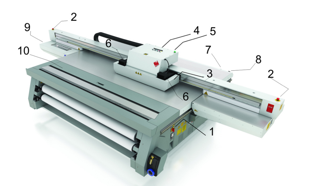
There are 3 emergency stop buttons located on the printer. Two on each end of the gantry and one on the work station.
You can see the two buttons on the gantry in the picture below. Highlighted as item 2.
Roll to Roll Operation
Loading a Roll
Loading the Roll to Roll Option
Step 1: On the dashboard click roll to roll setup
Step 2: Click Load, the feeder spool and the pickup spool with both rotate to the unlocked position.
Step 3: Load your roll of media on to the pickup spool. The printable side of your media must be face down.
Step 4: Using the Arizona Ruler position the roll into the middle of the machine to do this- match the size of the roll against the ruler.
Step 5: Lock the roll in place using the media clamps.
Step 6: Repeat steps 3 and 4 for your pickup roll, it is recommended that the width of this roll is the same as your media roll.
Step 7: Using the Roll to Roll foot pedals press the right button to feed the media through the media slot at the top of the machine, remember to feed the roll underneath the tension bar.
Step 8: Pull the media down under the light protector over your pickup spool and down so it is in line with your media spool. Pull the media tight and line it up so it will run square as printing.
Step 9: Use the left foot pedal to rewind the media keeping tension in the middle of the roll, attach the media to the pickup spool using masking tape in the middle and then work your way out to the edges placing masking tape every 400mm to 500mm to keep the tension.
Step 10: On the dashboard select the appropriate media profile then click the initialise. The media will then be tensioned and you will be able to print on the roll.
Unloading a Roll
Unloading the Roll to Roll Option
Step 1: On the dashboard click Roll to Roll Setup.
Step 2: Move the media forward onto the pickup roll to leave a little bit of extra cutting room. Click Load [not unload], the feeder spool and the pickup spool will both rotate to the unlocked position.
Step 3: Cut the media at the top of the Roll to Roll module using the cut line.
Step 4: Slide the pickup roll out of the machine at the right-hand side and manually roll the roll to pick up excess material. using masking tape wrap the excess around the roll. Place the spool back in place and use the media lock to unlock the clamps. You can now remove the roll.
Step 5: To remove the media roll repeat step 4 for the media roll.
Feed Rate Calibration
Cleaning & Maintenance
Printing a Nozzle Check
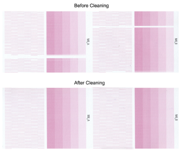
Once the print heads are clean you can now print to check the print quality, we usually print nozzle checks on a roll.
From the Arizona print station select to print on the roll, find the print nozzle check file, press print and start to begin.
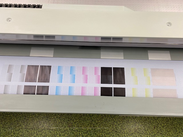
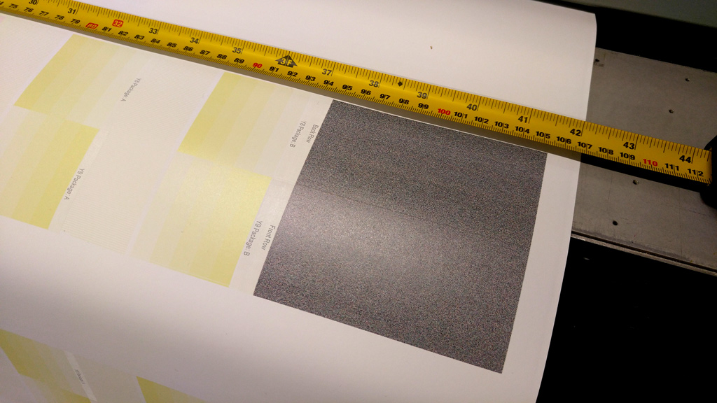
Once printed, you can check for any print issues from lines missing in the test print.
Check the previous test print if possible to see any print heads that are commonly out, you may not be able to fix them.
Cleaning the Printheads
Why?
The reason for cleaning the printheads is to remove any dust or grit the heads may pick up, which results in a poor print finish and potentially damaged printheads, which are expensive!
The cleaning process:
IMPORTANT Step 1:
For personal safety, we recommend that the operator always wear nitrile gloves, a protective
apron, and safety glasses with side shields when handling inks.
Step 2: Open the printhead tray under the nozzles.
Step 3: Press the first button on the right hand side to purge excess ink out of the heads.
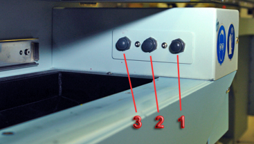
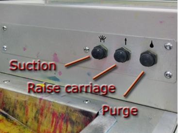
Step 4: Raise the print heads with button [2] in the middle to raise the carriage.
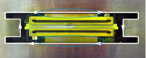
Step 5: Clean the edge of the excess ink tray with a fibreless cloth and use a dry swab to pick up any excess ink from around the edge of the printhead opening in the pan (see the white line with arrows in the image below). Take special care to remove any excess ink, flush or alcohol on the metal plate between the pan and the printhead (see the area covered by the two ellipses in the picture below). A single swab can be used for each colour channel or use it until the swab becomes saturated with ink.
Step 6: Press the third button away from you on the right-hand side to activate the vacuum. Use the head vacuum found on the left-hand side [make sure it's connected correctly] and clean it with the white fibreless cloth before use.
Step 7: Gently slide the vacuum along the print heads from left to right, making sure you get the slots of the vacuum piece into the printhead grooves. [you can leave the white heads to last]. Once you get the right connection you will hear the suction from the vacuum. In between each head clean, wipe the vacuum cleaner with the white fibreless cloth.
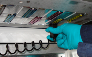
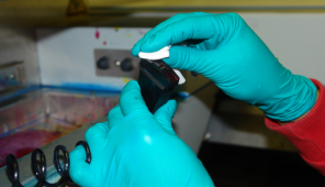
Step 8: Once all print heads are clean, you can turn off the vacuum and lower the print heads after use, then close the ink drip tray.
Step 8: Remove your latex gloves using the correct removal procedure.
Step 9: Assuming you have loaded basic paper on the roll. Go to the workstation to begin a print test. Press the button to turn on print to roll. Select the print test and begin print.
Step 10: Wait for the heads to heat up and it will then begin the test print.
Step 11: Checking the lines of the test print are correct there. Any missing lines could happen because of the heads not being cleaned properly or have always been missing, check previous test prints to check any patterns.
Changing ink
When to do:
An ink bag can be replaced at any time. Ink bags should be replaced if:
• The printer displays an "Error: ink fill timed out" message. This does not necessarily mean that
the ink bag is empty, but if you see it, check the level of ink remaining and change the bag if
needed. If you see the message and there is still ink in the bag, place a service call.
• The operator sees that the bag is empty.
• An ink bag is nearly empty and the operator wants to leave the printer unattended during a
long print and does not want the ink to run out. The nearly empty bag can be reconnected and
used up later when the operator is present.
NOTE
An ink bag can be changed during a print job. it is not necessary to stop the printer.
Safety Information - Use appropriate safety equipment - nitrile gloves and eye protectors. Take
precautions to avoid ink on your skin or in your eyes.
Where do we stock the new ink?:
You'll find our stock of ink bags in the wooden looking cabinet in the corner beside the door into the stock room.
Where to find the ink bag input?:
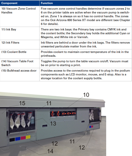
Procedure:
1. Open the clear plastic door on the Ink Station.
2. Identify the ink bag to be replaced.
3. Press the quick-release coupler button at the bottom corner of the ink bag.
4. Unhook the bag from the top of the ink station.
5. Replace with a new ink bag of the same colour.
6. Push the quick-release coupler at the bottom corner of the new bag into place.
NOTE
If you place a bag in the wrong ink station (for example, yellow ink in the black ink station) the display will show an error message and the printer will not print until the correct bag is installed.
Flatbed Operation
Loading Material
Loading Material
Select the material from the rack behind the Arizona (Other materials are found in the storage through the door).
Wearing gloves (to stop any finger marks from appearing). Pull the board over your head if possible and place it on to the print bed.

Masking Areas
Masking areas of the vacuum holes are useful to keep the pressure of the vacuum on the board.
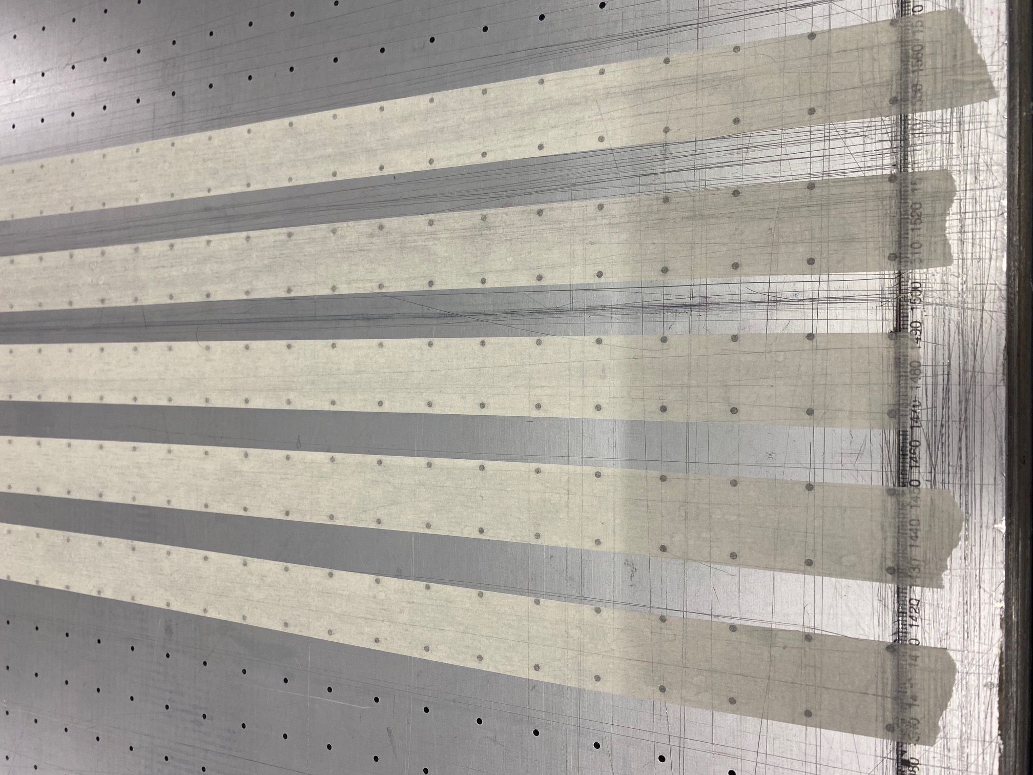
We also use masking tape to help the board stay flat on the bed.
If you only need to use a small section of the material, you can leave the film on partially. Simply score the film off of the section you'd like to print on. This helps keep your remaining section of material clean of any dust and marks.
Vacuum Areas
Introduction
The overlay sheet on the printer table creates a vacuum field, which is divided into zones by
magnetic strips on the underside. When the printer is shipped, the vacuum zones are configured
to support common metric or imperial media sizes. The zones are installed at the factory,
according to operator preference when the printer is ordered. The purpose of the vacuum zones
is to reduce the preprint setup time by reducing the need to mask the open area on the vacuum
table when printing on the most common-size media. The printer ships with a vacuum field
configured to support either metric or imperial size media.
For the Océ Arizona 600 Series GT vacuum control valve handles are used to manage these
zones. The printer has five control valves that determine the zones that are active when the table
vacuum pump is on. Zone 1 area is always active, and the five valves control zones 2 through 6.
The vacuum zones are open when the valve handles are vertical.
Purpose
The vacuum system holds the media in place. The zones described in this section are arranged to
accommodate common media dimensions.
Metric Vacuum Zones
NOTE THIS IS FROM FACTORY AND OUR PRINTER IS DIFFERENT
The following shows the locations and media dimensions associated with the factory-set metric
vacuum zones. The name of the zone indicates which vacuum handle controls that zone (except 1
as that zone is always on).
• Vacuum zone 1 = 600 x 800 mm
• Vacuum zone 2 = 700 x 1000 mm
• Vacuum zone 3 = 800 x 1200 mm
• Vacuum zone 4 = 1000 x 1400 mm
• Vacuum zone 5 = 1000 x 2100mm
• Vacuum zone 6 = 1250 x 2500mm
The metric configuration is designed such that zone 6 can be reconfigured by a service
representative from the 2.5m x 1.25m area size to 4'x8'.
Measuring the Head Height
To measure the thickness of the material choose the guage from the shadow board.
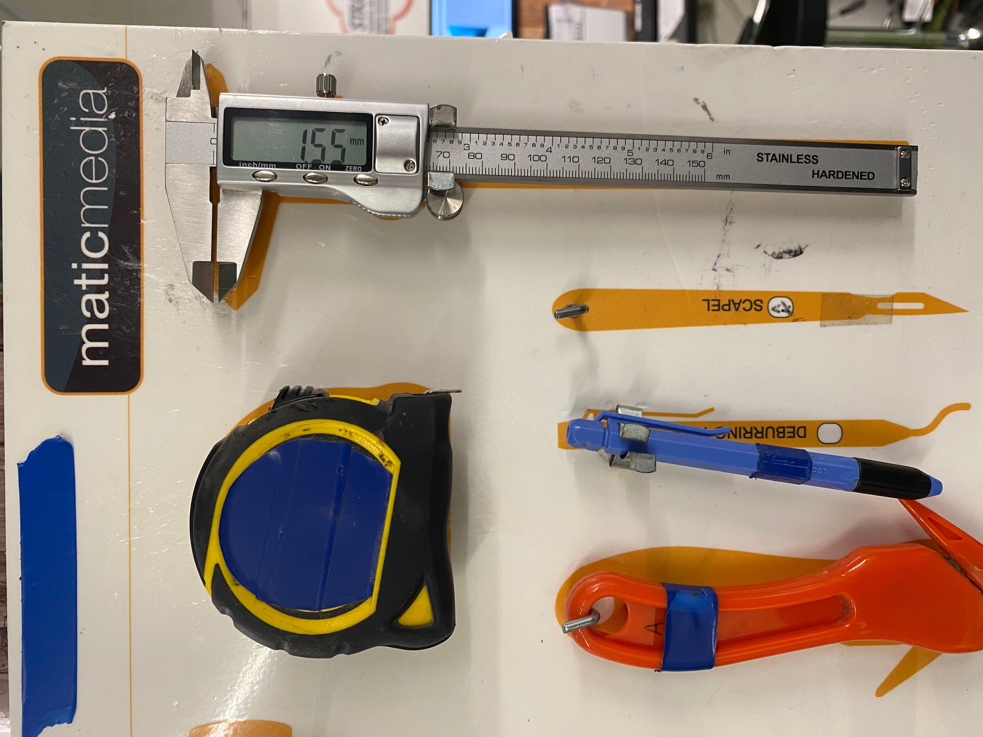
Take it to the material, and press ON.
Twist the cog on top to loosen the gauge slider.
Fit the material into the gauge and the screen will display the thickness in millimetres.
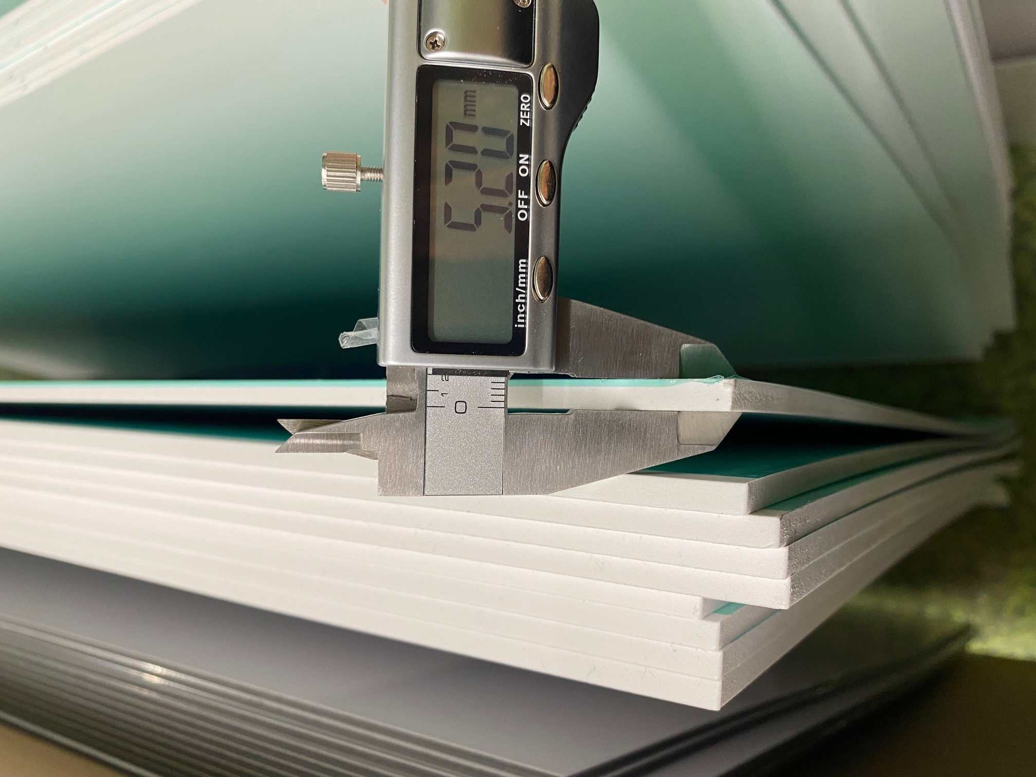
Once you select to print a job, the pop-up screen will appear with the option to input your head height.
Depending on the material, the normal height should be 0.5mm higher than the thickness of the material.
The higher the head the print will have a lower quality of print finish.
Printing a Nozzle Check
To begin a nozzle check on the flat bed, pick your material and size (big enough for the test size 1100x110mm).
Choose nozzle test on the top right of the screen.
Choose the flatbed option on job parameters 'type' so it looks like below.
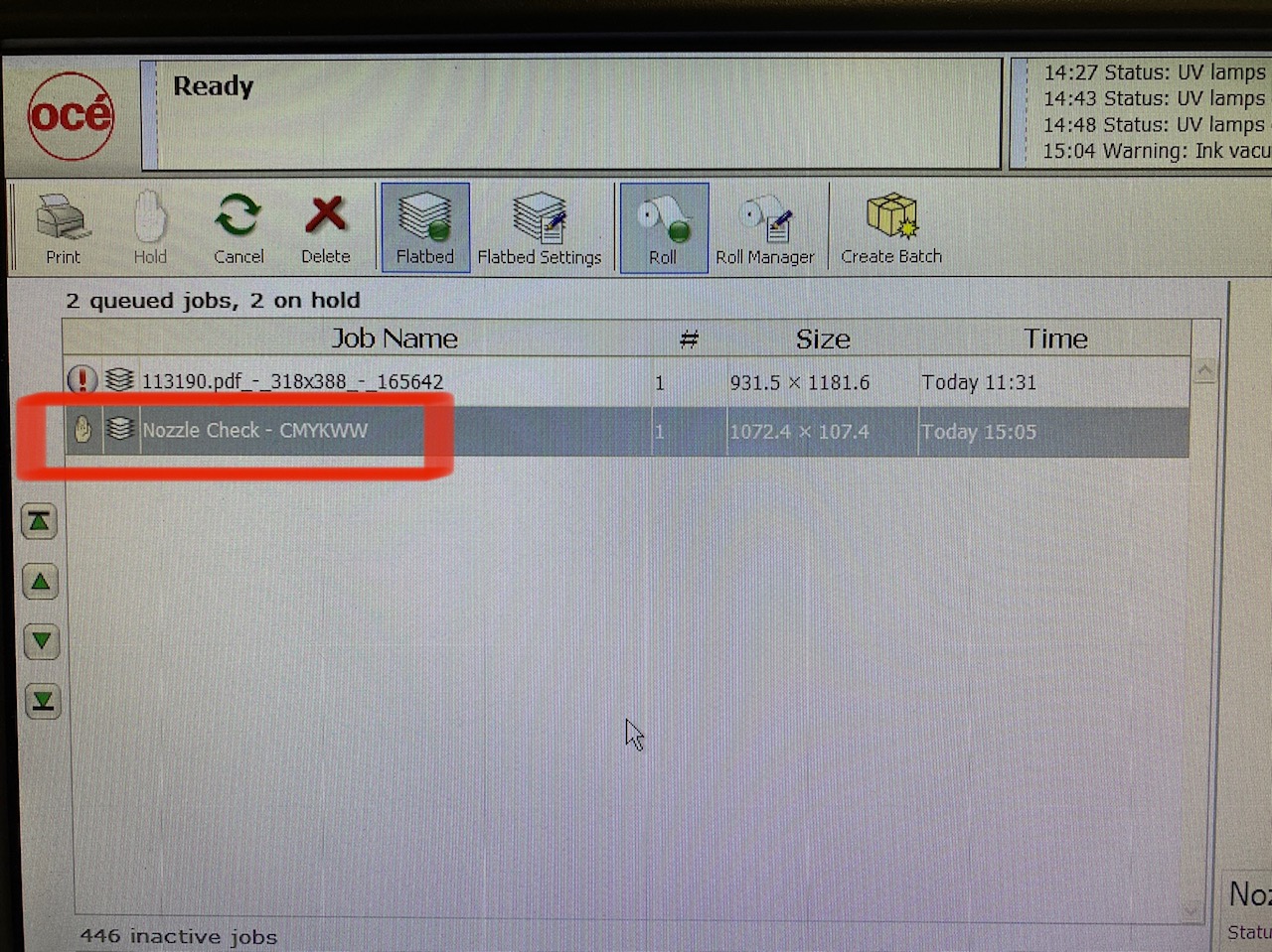
Once your material is secure on the bed, hit print and start.
Printing Rulers
Operating Panel - General Usage
Viewing Jobs
When selecting a job in Active Jobs List (6) or Inactive jobs (8) it will display the artwork in the job Placement Preview (7)
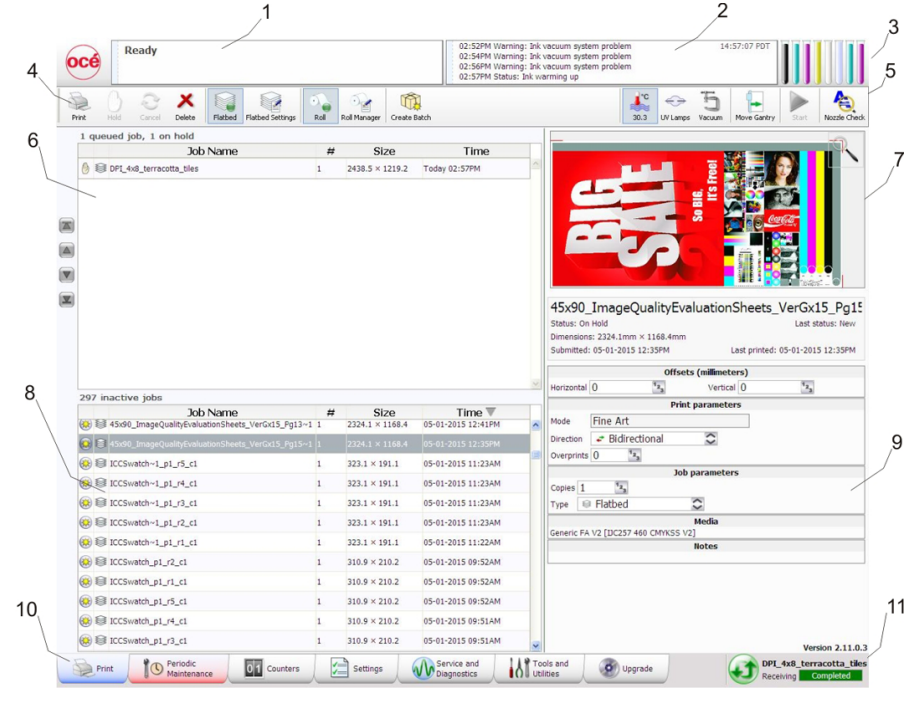
Viewing Print Layers
Position Jobs
To position a job- use the offsets panel on the right-hand side under the preview.

Starting from the bottom left of the artwork you can select the horizontal and vertical offset. This is based on setting a board on the bed at 0x0mm based on the ruler position printed on the bed.
Tip: Print your job closest to the print head in case of print issues you can save the rest of the board
Creating Batch Jobs
Sequential
Collated
Printing a Nozzle Check
Select Nozzle Check at the top right of the page (5)

This loads the pattern to print a nozzle check. Select if you'd like to print on the roll or on the bed (9) and then hit print.
Pausing Jobs
Select Hold to pause a job. (4)
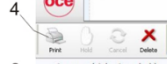
Cancelling Jobs
Select Cancel (4)
Deleting Jobs
Select Delete (4)
Operating Panel - Administrative Usage
Setting Network Address
Bulk Deleting Jobs
Outputting Maintenance Logs
Accessing Special Print Files
Accessing Usage Counters
Double Sided Printing
Maintenance
Changing Ink Bags
White Ink Agitation
Head Cleaning
Ink Filter Changing
Print Head Filter Changing
Changing the Lamps
Daily Maintenance Procedure
Weekly Maintenance Procedure
Troubleshooting
Troubleshooting
Oce User Manual
Turning the Arizona On, Off & Idle


